Beschreibung
Description:
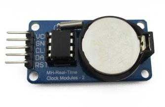
The DS1302 trickle-charge timekeeping chip contains a real-time clock/calendar and 31 bytes of static RAM. It communicates with a microprocessor via a simple serial interface. The real-time clock/calendar provides seconds, minutes, hours, day, date, month, and year information. The end of the month date is automatically adjusted for months with fewer than 31 days, including corrections for leap year. The clock operates in either the 24-hour or
12-hour format with an AM/PM indicator. Interfacing the DS1302 with a microprocessor is simplified by using synchronous serial communication. Only three
wires are required to communicate with the clock/RAM: CE, I/O (data line), and SCLK (serial clock). Data can be transferred to and from the clock/RAM 1 byte at a time or in a burst of up to 31 bytes. The DS1302 is designed to operate on very low power and retain data and clock information on less than 1µW. The DS1302 is the successor to the DS1202. In addition to the basic timekeeping functions of the DS1202, the DS1302 has the additional features of dual power pins for primary and backup power supplies, programmable trickle charger for VCC1, and seven additional bytes of scratchpad memory.
FEATURES
- ?Real-Time Clock Counts Seconds, Minutes, Hours, Date of the Month, Month, Day of the Week, and Year with Leap-Year Compensation Valid Up to 2100
?31 x 8 Battery-Backed General-Purpose RAM
?Serial I/O for Minimum Pin Count
2.0V to 5.5V Full Operation
Uses Less than 300nA at 2.0V
Single-Byte or Multiple-Byte (Burst Mode)
Data Transfer for Read or Write of Clock or RAM Data
?Simple 3-Wire Interface
TTL-Compatible (VCC = 5V)
Optional Industrial Temperature Range: -40°C to +85°C
?DS1202 Compatible
4duino Example Sketch:
|
Code:
/* FILE: ARD_1302_RTC_Example_Sketch_HCMODU0035
DATE: 03/09/13 VERSION: 0.1 REVISIONS: 20/09/13 Created version 0.1 This is an example of how to use the Hobby Components 1302 Real Time Clock module (HCMODU0035). This example uses the RTC library written by Henning Karlsen (http://www.henningkarlsen.com/electronics/). This example sketch demonstrates how to read and write to the RTC module. To connect the module to your Arduino please see the following pinout: PINOUT: MODULE ARDUINO GND GND VCC +5V SCK D4 I/O D3 RST(CS) D2 You may copy, alter and reuse this code in any way you like, but please leave reference to HobbyComponents.com in your comments if you redistribute this code. This software may not be used for the purpose of premoting or selling products that directly compete with Hobby Components Ltd’s own range of products. THIS SOFTWARE IS PROVIDED „AS IS“. HOBBY COMPONENTS MAKES NO WARRANTIES, WHETHER EXPRESS, IMPLIED OR STATUTORY, INCLUDING, BUT NOT LIMITED TO, IMPLIED WARRANTIES OF MERCHANTABILITY AND FITNESS FOR A PARTICULAR PURPOSE, ACCURACY OR LACK OF NEGLIGENCE. HOBBY COMPONENTS SHALL NOT, IN ANY CIRCUMSTANCES, BE LIABLE FOR ANY DAMAGES, INCLUDING, BUT NOT LIMITED TO, SPECIAL, INCIDENTAL OR CONSEQUENTIAL DAMAGES FOR ANY REASON WHATSOEVER. */ /* Define the DIO pins used for the RTC module */ #define SCK_PIN 4 #define IO_PIN 3 #define RST_PIN 2 /* Include the DS1302 library */ #include <DS1302.h> /* Initialise the DS1302 library */ DS1302 rtc(RST_PIN, IO_PIN, SCK_PIN) void setup() { /* Clear the 1302’s halt flag */ rtc.halt(false) /* And disable write protection */ rtc.writeProtect(false) /* Initialise the serial port */ Serial.begin(9600) } /* Main program */ void loop() { /* Set the time and date to 16:30 on the 3rd of September 2013 */ rtc.setDOW(MONDAY) rtc.setTime(16,30,0) rtc.setDate(3, 9, 2013) /* Read the time and date once every second */ while(1) { Serial.print(„It is „) Serial.print(rtc.getDOWStr()) Serial.print(“ „) Serial.print(rtc.getDateStr()) Serial.print(“ „) Serial.print(„and the time is: „) Serial.println(rtc.getTimeStr()) /* Wait before reading again */ delay (1000) } } |


Bewertungen
Es gibt noch keine Bewertungen.